|
Hardware Required
- MSPM0G3507 LaunchPad™ Development Kit (LP-MSPM0G3507)
- ECE445M Robot board v7.1
- ESP8266
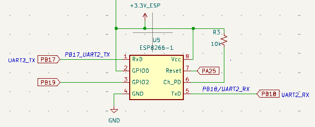
Pin assignments
- ESP8266 1 URxD = PB17 = UART2 out of MSPM0, into ESP8266 115200 baud
- ESP8266 2 GPIO0 = +3.3V for normal operation (ground to flash)
- ESP8266 3 GPIO2 = PB19 = GPIO, high/float on startup, has internal pullup, can be used for I/O
- ESP8266 4 GND = Gnd = GND (70mA)
- ESP8266 5 UTxD = PB18 = UART out of ESP8266, UART2 into MSPM0 115200 baud
- ESP8266 6 Ch_PD = chip select, 10k resistor to 3.3V
- ESP8266 7 Reset = PA25 = MSPM0 GPIO output, can issue output low to cause hardware reset
- ESP8266 8 Vcc = regulated 3.3V supply with at least 70mA
- I2C SCL: PB2 is the SSD1306 SCL
- I2C SDA: PB3 is the SSD1306 SDA
- Input: PA18 is S2 positive logic switch, index 39 in IOMUX PINCM table
- Input: PB21 is S3 negative logic switch, index 48 in IOMUX PINCM table
The first version of the Motor board (v7) uses UART1 on PA17 and PA18.
LaunchPad Jumpers
- Remove J16 J17 J18: Disconnects light sensor from the microcontroller PA22 PA27 PA26
- J4: Connects PA0 to red LED
- J5: Connects PB22 to blue LED2
- J6: Connects PB26 to red LED2
- J7: Connects PB27 to green LED2
|